Description
Used for 1000Base-T – 2.5G/5G/10GBase-T
1000BaseT
- Peak differential output voltage (IEEE Std 802.3™‐2022 – 40.6.1.2.1)
- Maximum Output Droop (IEEE Std 802.3™‐2022 – 40.6.1.2.2)
- Differential output templates (IEEE Std 802.3™‐2022 – 40.6.1.2.3)
- Transmitter Distortion (IEEE Std 802.3™‐2022 – 40.6.1.2.4)
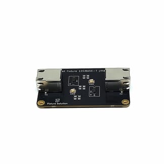
- Jitter Master & Slave Mode (IEEE Std 802.3™‐2022 – 40.6.1.2.5)
- Clock Frequency (IEEE Std 802.3™‐2022 – 40.6.1.2.6)
Testing shall be done on all 4 Pairs A, B, C and D.
Beside a suitable oscilloscope a suitable differential probe is required for the following measurements.
| Pattern | Criteria | |
| 40.6.1.2.1 | ||
| Voltage Point A | Test Mode 1 | 670 mV <= x <= 820 mV |
| Voltage Point B | Test Mode 1 | 670 mV <= x <= 820 mV |
| Voltage Point A B difference | Test Mode 1 | x <= 1 % |
| Voltage difference between Point C and AVG(A,B)/2 | Test Mode 1 | x <= 2 % |
| Voltage difference between Point D and AVG(A,B)/2 | Test Mode 1 | x <= 2 % |
| 40.6.1.2.2 | ||
| Voltage magnitude at point G versus point F | Test Mode 1 | x >= 73.1 % |
| Voltage magnitude at point J versus point H | Test Mode 1 | x >= 73.1 % |
| 40.6.1.2.3 | ||
| Differential Output Templates | Test Mode 1 | Multiple Mask for A, B, C, D, F and H |
| 40.6.1.2.4 | ||
| Transmitter Distortion – Minimum peak distortion | Test Mode 4 | x < 10 mV |
| Percentage of eye opening within limit | Test Mode 4 | x >= 60 % |
| 40.6.1.2.5 | ||
| Jitter Master Mode – Unfiltered TIE jitter | Test Mode 2 | x <= 1.4 ns |
| Jitter Master Mode – Filtered TIE jitter | Test Mode 2 | x <= 300 ps |
| Jitter Master Mode – Transmitter Clock Frequency | Test Mode 2 | 124.9875 MHz < x < 125.0125 MHz |
| Jitter Slave Mode – Unfiltered TIE jitter (without TX_CLK approach) |
Test Mode 2 Test Mode 3 |
x <= 1.4 ns |
| Jitter Slave Mode – Filtered TIE jitter (without TX_CLK approach) |
Test Mode 2 Test Mode 3 |
x <= 400 ps |
1000BaseT Test Mode 1
![]()
1000BaseT Test Mode 4
![]()
2.5GBaseT
- Maximum output Droop (IEEE Std 802.3™‐2022 – 126.5.3.1)
| 126.5.3.1 | Pattern | Criteria |
| Maximum output Droop | Test Mode 6 |
5GBaseT
- Maximum output Droop (IEEE Std 802.3™‐2022 – 126.5.3.1)
| 126.5.3.1 | Pattern | Criteria |
| Maximum output Droop | Test Mode 6 |
10GBaseT
- Maximum output Droop (IEEE Std 802.3™‐2022 – 55.5.3.1)
| 55.5.3.1 | Pattern | Criteria |
| Maximum output Droop | Test Mode 6 |